ErgoDox Wireless Getting Started Guide
This is the "getting started" guide for the ErgoDox Wireless for purchases August 2021 and later.
It is strongly suggested that you read through this guide carefully before proceeding with your kit. Most likely you are new to ZMK and the setup process is different from what you are used to.
If you have questions, please join the Discord.
General Recommendations
- Wear surgical gloves or wear an anti-static strap when handling the PCB (circuit board) to minimize the chances of damaging the electronic components with electrostatic discharge.
- Be extremely careful when detaching the battery (though generally you will not need to). Using excessive force can rip the battery connector off the PCB.
PCB Buttons
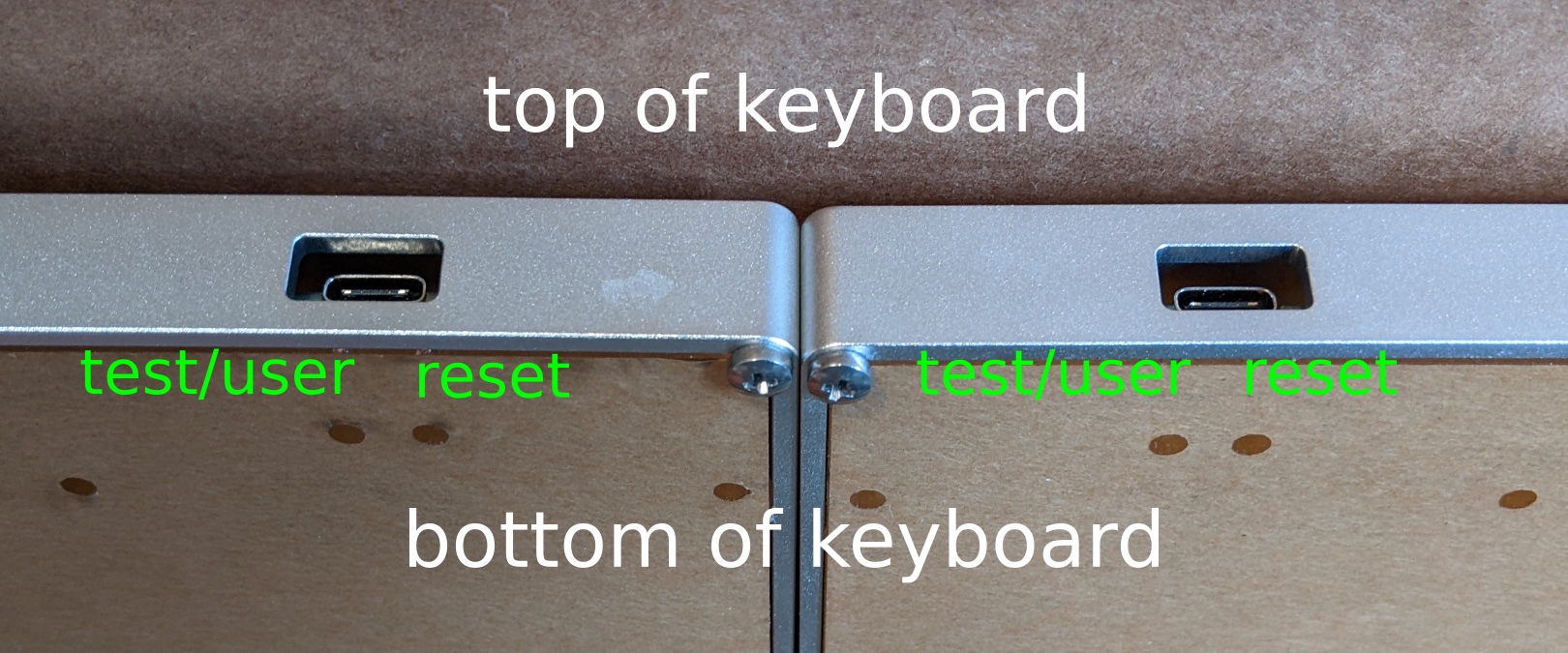
Each keyboard half has two buttons on the bottom of the PCB. They can be accessed through the holes on the bottom acrylic layer.
If you look at the USB C port with the keyboard facing up:
-
The button on the right side is the reset button.
- Pressing the button once will reset/reboot the keyboard half. The user LED will be red briefly following the reboot.
- Pressing the button twice within 500ms will put the keyboard half into bootloader mode.
- If the LED is RGB, it will be solid green while in bootloader mode.
- If the LED is not RGB, it will be red and pulse slowly in bootloader mode.
- If you want a mnemonic for remembering which button is which, "right" and "reset" both start with "r" and are 5 letters.
-
The button on the left side is the off button.
- When a keyboard half is off, pressing any of the keyboard keys will have no effect and consume no battery.
- If the LED is RGB, it will be solid white for one second while the keyboard is turning off.
- If the LED is not RGB, it will be solid red for one second while the keyboard is turning off.
- Press the reset button to turn the keyboard back on. The user LED will be red briefly following the reboot.
- The off button is not yet implemented on the "central" keyboard half (the left half in a dongleless setup). This will be added via a firmware upgrade in the near future.
- When a keyboard half is off, pressing any of the keyboard keys will have no effect and consume no battery.
Battery
Depending on the shipping destination and shipping service, the battery may or may not be connected. To determine if the battery is connected, start by pressing the reset button once.
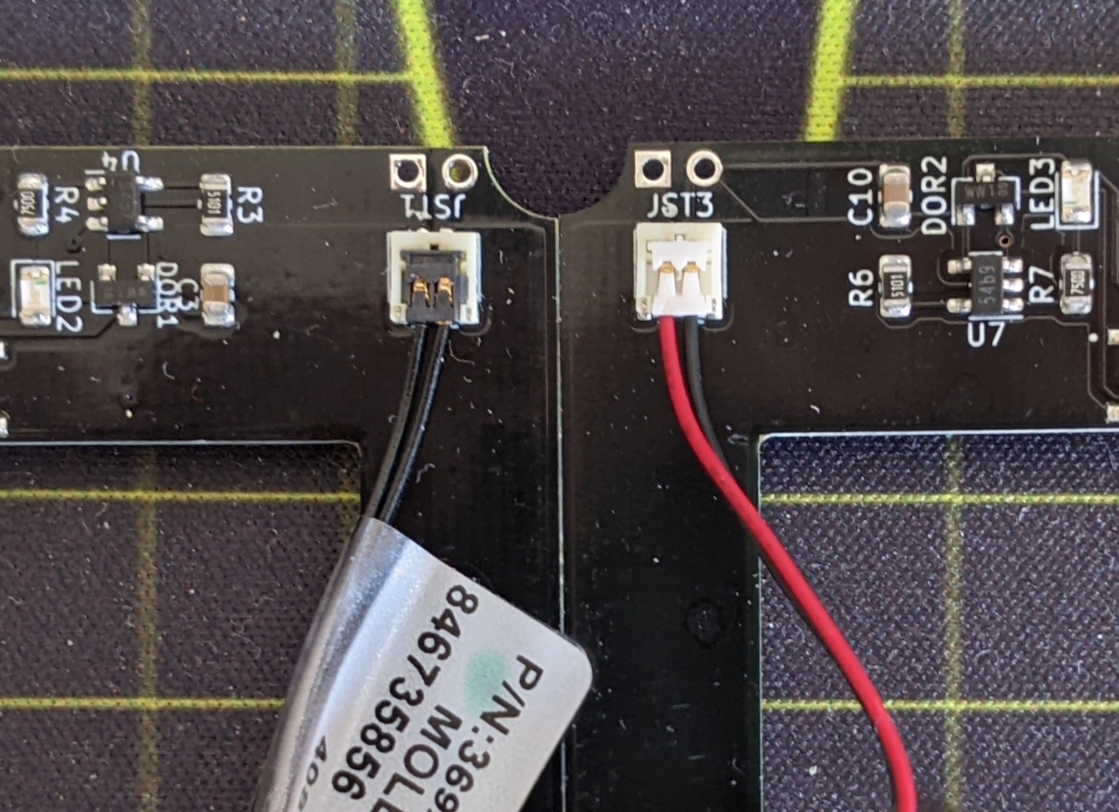
If the user LED blinks twice, the battery is already connected; proceed to the next section. If nothing happens after pressing the reset button, the battery is not connected. Open the case and attach the battery as shown in the following image. Make sure that the battery "clicks" in the connector. Be careful and do not use excessive force as the connector can be fragile.
- For solar keyboards, the battery is connected via the solar PCB. A black cable connects the solar PCB to the keyboard PCB as shown on the left.
- For non-solar keyboards, the battery is connected directly to the keyboard PCB via a red/black cable as shown on the right.
Initial Firmware
Most keyboards are preloaded with a "matrix testing" firmware. This firmware will turn on the user LED when a switch is pressed. This provides an easy way of testing whether each switch has been installed correctly or if a switch pin was bent during insertion.
A small subset of keyboards is shipped with the production keyboard firmware rather than the testing firmware. This is likely the case if the battery is connected but no LED turns on when pressing the keyboard switches. If this is the case for your keyboard, please proceed with this guide but skip the "Peripheral Flashing" and "Initial ZMK/Central Flashing" sections.
Switch Installation
- If your keyboard came with foam preinstalled, loosen the screws slightly before installing the switches so the plate and PCB can realign if necessary.
- Start by installing switches in the corners. This ensures that the plate is completely aligned with the PCB before the rest of the switches are installed.
Bootloader Mode
To update the firmware running on a dongle or keyboard half, it should be connected via USB and put into bootloader mode. All dongles/keyboards are shipped with an UF2 bootloader. While in bootloader mode, you will see a virtual flash drive on your computer.
- The virtual drive for the dongle will be named
MDBT50QBOOTorNRF52BOOT(depending on the dongle). - The virtual drive for the keyboard halves will be
SliceMK.- It is recommended that you do not have both halves connected via USB and in bootloader mode at the same time (it's fine if they are plugged in for charging but not in bootloader mode). If you do, it will be difficult to identify which is the left and which is the right as the drives would be named identically. Depending on the operating system, it's also possible that only one of the two is visible.
Firmware files have the .uf2 extension. To flash a firmware file, simply copy it to the virtual drive.
Please double check that you are flashing the correct file into the correct device.
- Make sure the firmware is for the correct dongle and/or PCB version.
- Do not flash the dongle firmware onto either keyboard half or vice versa.
- Do not flash the left half firmware onto the right half or vice versa.
A few notes about the UF2 bootloader:
- Depending on your operating system, you may encounter an ejection or file copy error. This is expected and not a bug.
- If you subsequently return to bootloader mode, the UF2 file that you copied earlier will no longer be there. This is expected; the bootloader drive is a virtual drive and merely a transport mechanism.
- If the virtual drive does not disappear after copying the firmware file, most likely there is a compatibility issue. You should double check that the firmware is for the correct PCB version.
Dongles
There are currently three dongle options.
- Raytac MDBT50Q-RX Dongle
- Hold button while plugging in to enter bootloader for the first time.
- Press button to enter bootloader once ZMK has been loaded.
- SliceMK USB C Dongle MDBT50Q Blue
- Press button twice in 500ms to enter bootloader.
- Nordic nRF52840 Dongle
- Press white button twice in 500ms to enter bootloader.
Split Communication
Before flashing the production keyboard firmware, it's important to understand how the keyboard halves communicate with each other and your computer. Please read this section but do not flash anything just yet.
If you are using a dongle:
- The dongle is the "central" and handles the keyboard logic. The two keyboard half "peripherals" will send data to it.
- When building the firmware with the keymap configurator, select your dongle as the "Build Target".
- Flash
zmk-dongle.uf2from the keymap configurator onto the dongle. Flashperipheral-left.uf2andperipheral-right.uf2onto the left and right halves respectively (these files are linked in the next section).
If you are not using a dongle:
- The left is the "central" and handles the keyboard logic. The right half "peripheral" will send data to it.
- When building the firmware with the keymap configurator, select the "Keyboard Left Half" option matching your PCB version as the "Build Target".
- You should flash
zmk-left.uf2from the keymap configurator onto the left half. You should flashperipheral-right.uf2onto the right half (this file is linked in the next section).
A few notes about the central/peripheral setup:
- When you make changes to your keymap, you only need to update the central (the dongle if you are using a dongle, the left half if you are not using a dongle).
- Generally, it's not necessary to flash the peripheral(s). The only exception is when there are changes to the wireless communication protocol, in which case it would be made clear in the firmware upgrade instructions.
- You cannot use a peripheral half directly. If you connect a peripheral half via USB, it will not output anything. Keyboard data always goes through the central.
Peripheral Flashing
If you have a dongle, make sure it is not plugged in while flashing the peripheral halves.
Start by flashing the right keyboard half with the peripheral firmware:
- Connect the right keyboard half over USB.
- Place the right half into bootloader mode (see PCB Button section for how to do that). The user LED should pulse slowly.
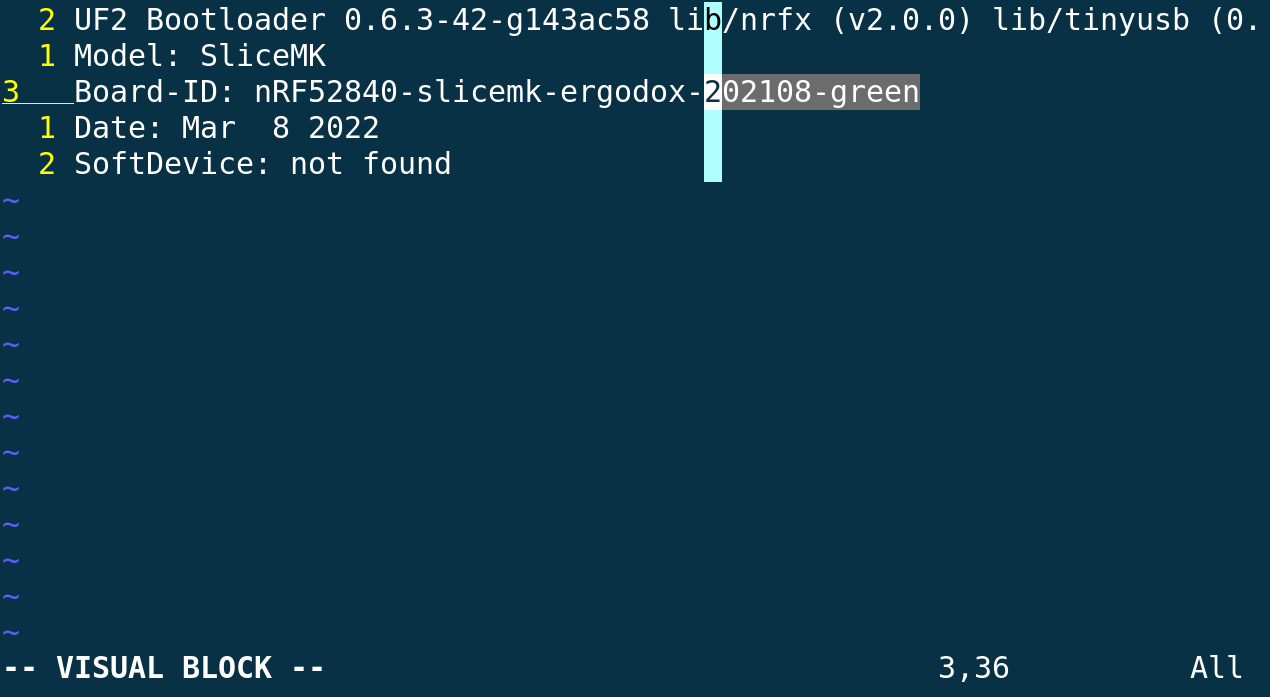
- In the virtual drive, open
INFO_UF2.TXT. TheBoard-IDline should identify the PCB version.
- Download the
peripheral-right.uf2firmware (download page) matching the PCB version. - Copy
peripheral-right.uf2to theSliceMKdrive. The user LED will flash very quickly while it's flashing. The user LED will turn off when flashing is complete. - Unplug USB cable for the right half.
- Press reset once to reset/reboot the right half. The user LED should blink twice.
If you are not using a dongle, proceed to the next section.
If you are using a dongle, repeat the above steps with the left half (using peripheral-left.uf2 where appropriate). Make sure to check the PCB version again as it may be different for the two halves.
Keymap Configuration
You can configure your keyboard layout using the keymap configurator. When building the firmware, make sure to select the correct "Build Target". If you are using a dongle, that would be the dongle. Otherwise select the "Keyboard Left Half" option matching your PCB version of the left keyboard half.
For the initial build, keep the example keymap as is including the "testing" layer. This layer is designed to help you easily test that all your keys are working.
Initial ZMK/Central Flashing
If the central is a dongle:
- Build the firmware using the keymap configurator.
- Plug in the USB dongle.
- Place the dongle in bootloader mode. The user LED should pulse slowly while in bootloader mode.
- Ensure that it has been at least 15 seconds since resetting both peripherals halves (the final step in Peripheral Flashing section).
- Copy
zmk-dongle.uf2to the dongle virtual drive. The user LED will flash very quickly while it's flashing. The user LED will turn off when flashing is complete. - Unplug the dongle and plug it back in.
- Press a few keys on the keyboard halves. Give it a couple of seconds for them to bond with the dongle. Both halves should work after this is complete.
If the central is the left half:
- Build the firmware using the keymap configurator.
- Connect the left keyboard half over USB.
- Place the left half in bootloader mode. The user LED should pulse slowly.
- Ensure that it has been at least 15 seconds since resetting the right peripheral half (the final step in Peripheral Flashing section).
- Copy
zmk-left.uf2to the left half's virtual drive. The user LED will flash very quickly while it's flashing. The user LED will turn off when flashing is complete. - Press reset once to reset/reboot the left half. The user LED should blink twice.
- Press a few keys on the left keyboard half. It should work like a regular USB keyboard.
- Press a few keys on the right keyboard half. Give it a couple of seconds to bond with the left keyboard half. Both halves should work after this is complete.
Key Testing
Use the "testing" layer to confirm that all the keys are working.
Keymap Modifications
Once you have confirmed that all the keys are working, you can delete the layer so the "main" layer becomes the default layer and build the new firmware.
To update the keymap:
- Place the central in bootloader mode. The user LED should pulse slowly.
- Copy
zmk-dongle.uf2to your dongle orzmk-left.uf2to your left half. The user LED will flash very quickly while it's flashing. The user LED will turn off when flashing is complete. - Press keys on peripheral(s) and give the centrals a couple of seconds to reconnect.
Each time you modify your keymap, make sure to keep a copy of the slicemk_ergodox.json file from the build archive. You will need it to make changes to your keymap. Your keymap will be automatically deleted from the build server after a couple of hours.
Laser Cutting Paper
You should decide whether you want to leave on or peel off the laser cutting paper. Functionally it doesn't make much of a difference.
We recommend removing the laser cutting paper for the bottom acrylic layer as it is a bit nicer aesthetically and it makes the PCB version number visible without having to disassemble the case.
If your case includes foam, we recommend keeping the laser cutting paper on that as it provides a bit of additional height/cushion.
Rubber Feet, Tenting, and Full Hand Plate
- If you purchased a tenting kit and/or full hand plate, please use the designated holes to position the rubber feet on the keyboard. They are there so you can detach the keyboard and use it on its own with the rubber feet.
- You should place the rubber feet after you decide whether you want the laser cutting paper to remain on the bottom layer.
- If you are not using your keyboard with the tenting kit or full hand plate, the rubber feet placement is not important.
- Additional rubber feet can be placed on the full hand plate to prevent the keyboard screws from making contact with your desk. Their placement is not important.